Example
The following is a partial example of an electric coffee maker.
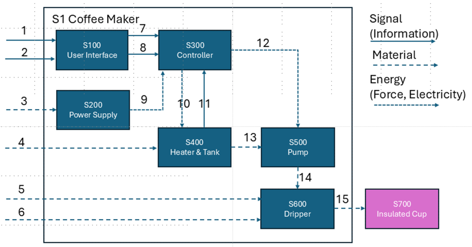
A customer wants to make a cup of hot coffee. The team’s concept is an electric coffee maker that uses a drip method. Figure 1 shows the flow diagram of the system architecture. The team chose not to design an insulated coffee cup (S700).

Figure 1 System Architecture Flow Diagram
The following tables summarize interactions among the subsystems.
Table 1. UI (User Interface) Subsystem Interface (S100)| No. | Source Subsystem (from) and Inputs (Interface) | Destination Subsystem (to) and Outputs (Interface) | Notes |
|---|---|---|---|
| 1 | 1. A user selects the amount of coffee to be made. | ||
| 2 | 2. A user selects Start. | Pre-Condition: The amount of coffee to be made must be selected. | |
| 3 | 7. Send the amount of coffee to be made to the S300 Controller. | ||
| 4 | 8. Send the start command to the S300 Controller. |
| No. | Source Subsystem (from) and Inputs (Interface) | Destination Subsystem (to) and Outputs (Interface) | Notes |
|---|---|---|---|
| 1 | 3. Electricity from a wall power outlet. | 110V AC | |
| 2 | 9. Power for the controller (S300), the water heater (S400), and the dripper pump (S500). | low voltage DC |
| No. | Source Subsystem (from) and Inputs (Interface) | Destination Subsystem (to) and Outputs (Interface) | Notes |
|---|---|---|---|
| 1 | 7. The amount of coffee to be made from the S100 User Interface subsystem. | 110V AC | |
| 2 | 8. The start command from the S100 User Interface subsystem. | ||
| 3 | 9. Power from the S200 Power Supply. | ||
| 4 | 10. Send power for heating water to the S400 Heater & Tank subsystem. | ||
| 5 | 11. Water temperature from the S400 Heater & Tank subsystem. | ||
| 6 | 12. Power for running a pump to the S500 Pump subsystem. | The pump must not be started when the water is cold. |